You may have seen this imposing building during your travels in the Great Haseley area of Oxfordshire. Sadly, it has fallen into neglect and the years have taken their toll. A major restoration project is now underway, aiming to return this historic building to its former glory. Follow the progress of the restoration in our blog....


The Restoration Team

Wednesday, 8 May 2013

Stoop and build 'em up

So, the next stage is upon us; relocating the cap to the mill and rebuilding there, in preparation for hoisting onto the tower. Luckily, the weather has been fine and we have made lots of progress in the last couple of weeks.

The main cap frame timbers arrive!

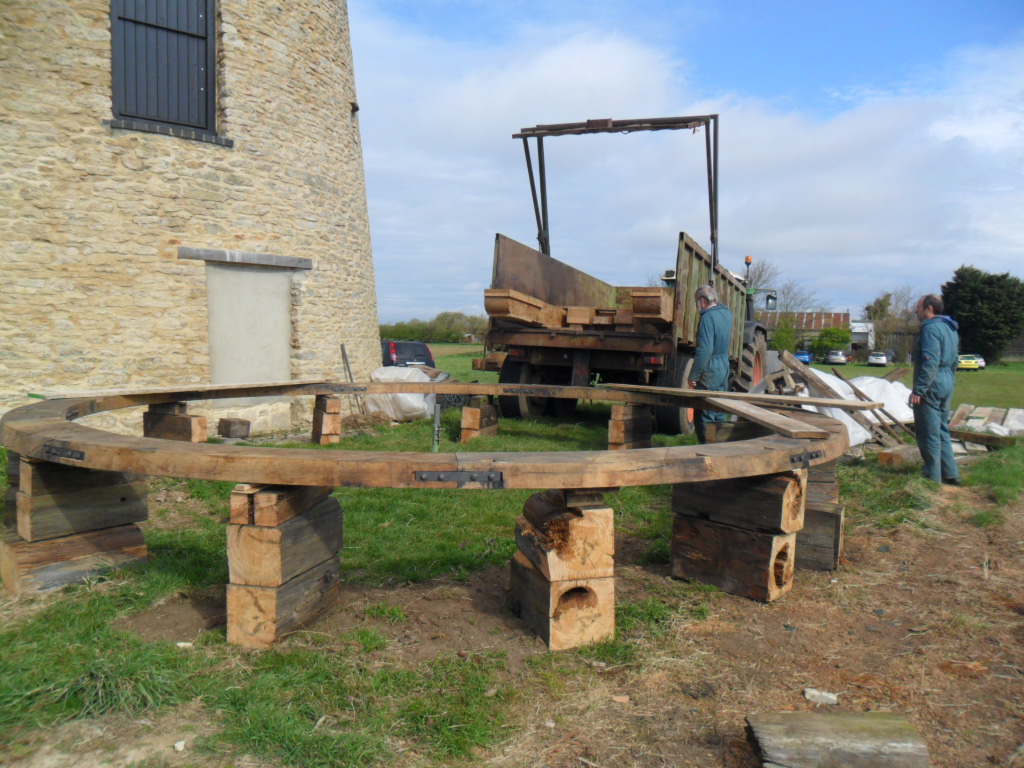
The cap circle already laid out on blocks (the blocks were made from the old sail stock - you can see how badly decayed it was down the middle)

The shears offloaded

The frame and fan booms assembled

Next we raised the lower finial section with a tripod - ready to receive the cap ribs...

Hoisting the finial

First ribs going in

The more you add, the stronger it gets!

Errr, how do I get down


With all the ribs fitted, and the ring purlin attached. Very aesthetically pleasing.
After that, with the storm hatch and fan door areas reassembled, we began boarding out the cap. Some of the boards were salvaged from the previous cap, probably enough to cover about one half. We will use new douglas fir boards to complete.


Sunday, 21 April 2013

Update

How time flies. So, after a few months of inactivity, we are all hands to the pumps again. The fan has been finished, and its staging has been trial fitted to the cap.
Rear of cap, with fan booms fitted and doorway made. Beginnings of fan gearing supports also visible.

The fan, 12 feet in diameter, with associated ironwork.


The next major task is to take down the cap, and reassemble it next to the mill. It can then be weather-boarded and lifted onto the mill. For a previous project at Wheatley windmill, the cap was completed at the workshop and transported as a whole unit to the mill. However, the Great Haseley cap is significantly larger, so this was not viable.

Meanwhile, another crucial piece of the cap, the finial, has been made by David Field http://www.davefield3d.co.uk/#/blog/4574986616/Making-the-Finial-for-the-Great-Haseley-Windmill-restoration-project./5255498

Making the GRP finial
 This will sit atop the wooden base portion of the finial (into which the cap ribs are located), the fit between the two having been designed to provide weatherproofing at this vulnerable part of the mill.

Thursday, 20 December 2012

Fan staging

With the continuing wet/dismal/cold weather, we have moved indoors to start work on the staging for the fan. The purpose of the fan is to keep the cap pointing into wind, so that the sails are properly aligned. Old photographs show the design of the staging, which supported the fan and its associated gearing. We are relying on this evidence, along with a drawing of the mill from the 70s, as there were no physical remains when we started the restoration.

The whole staging will rely on two sturdy beams (the fan 'booms') which will locate in the tail beam of the cap. These then project out of the rear of the cap. We are making the fan booms, and the associated staging, as a separate 'unit' indoors. As with the cap, this will then be taken down and rebuilt on site, prior to the whole lot being lifted on by crane.

Initial laying out of fan booms and joists


Joists housed into the booms, and uprights added, with bracing
The 'axle' for the fan will sit across the top of the two uprights. It is a large fan, 12 feet in diameter; in keeping with such a large cap. We are in the early stages of making this - we may need a bigger workshop!

Sadly, some of the gearing parts which linked the fan to the cap have disappeared over the course of time. So, we have also been welding/fabricating, as well as pattern making for casting of replacement parts.

There will be no more blog posts for a little while, so have a good festive break and check back with us in the New Year for further news!......


Wednesday, 14 November 2012

How do you raise a cap?

With difficulty! There should be a word for fitting rafters to to make a windmill cap roof..... Well, if it's good enough for barns, it's good enough for windmills; so I'll call it raising. Anyway, that is the stage we reached today. We have trial fitted the ribs in place, using a temporary pattern instead of the actual finial (we'll leave that challenge until we assemble the cap for real on-site). This was a tricky procedure, especially for the first few ribs, but the more we added, the easier it became. By the end of the day, we had all the tenoned ribs in place - that leaves us with the tapered ones to fit in-between.

Wow, it's starting to look like a windmill
Other items from the previous few days:

The braces for the truck wheels have been finished and fitted;

Two of the four new truck wheel braces

and we have made a start on the storm hatch and neck block

Starting the storm hatch; the weather studs fitted to the weather beam

The old neck block (supports the bearing for the windshaft), doesn't look too bad from this angle


From beneath, doesn't look quite so good!
Starting to make a new neck block

Thursday, 8 November 2012

Sunshine, and some more framing

Hoorah, dry weather. With the basic cap frame set up and lowered back onto the cap circle, attention has now turned to the additional frame members. The two diagonal braces between the weather beam and shears had somehow escaped the decay which affected the other beams, so we have reused these and fitted them into place. We have also reused the central block between these two braces, and made two new 'closers' which fill the gaps either side of this.

Diagonal braces fitted

Presumably, these braces originally helped spread the load from the weather beam to the cap circle, as well as stiffening the frame to resist thrust from the sails.

The cap is kept in position laterally by cast iron 'truck wheels' which rotate against the inside of the curb. Four of these were hung off diagonal struts running between the outside of the shears and the cap circle. We are having to remake these, as the originals had, you guessed it, decayed.

Making one of the new truck wheel supports (shown here upside down); lapped dovetail will fit into cap circle

Wednesday, 7 November 2012

Cap framing in the rain


Having chosen to build the cap outside, we are having to work in (brief) windows of fine weather. The sprattle and tail beam are now morticed in, so the basic cap frame is together.


The sprattle and tail beam in place


Closer view; with wedging space on the sprattle

Oh, it's raining again. What a change.


At least we've got the hang of arranging the tarpaulin now, so we don't have an olympic sized swimming pool to drain off every morning.

Sunday, 4 November 2012

Heavy cap timbers

As promised, a further update on the cap construction....

Having taken delivery of some rather hefty sections of oak, we are now in a position to start building up the main cap structure. First up, the two large beams which run front to back in the cap, the 'shears'. Here we see one of the shears in position, being cleaned up prior to being notched over the cap circle. Large timbers call for large planes!

Shear being cleaned up

With both shears cleaned up and notched into place, next came the transverse beams. The next photo is looking from the front of the cap towards the rear. So, we have, from front to back, the weather beam, sprattle beam and tail beam.


The weather beam and tail beam will support the front and rear ends, respectively, of the windshaft. The sprattle beam is effectively in the centre of the mill and will locate and support the top end of the main upright shaft.

The next two shots show some detail of how these beams are located in the shears.

Dovetail joint between weather beam and shear

Tenons at ends of weather beam and sprattle
The tenons on the sprattle (upside down in this shot) are cut to allow for wedging of the beam into position. This gives some scope for adjustment, so the upright shaft can run true. In contrast, the tail beam will be a direct fit. So, next job, morticing..........